HT77xx Series Guide: Efficient Step-Up Power for 2.7V-5V Projects {TL00008}

The HT7750 is a high-efficiency synchronous step-up (Boost) DC/DC converter designed for applications where a stable 5V output is required from a lower input voltage. Part of the HT77xx series, it is widely used in battery-powered devices because of its low start-up voltage and minimal power consumption.

This guide explores the features, variants, and practical implementation of the HT7750 boost converter.


Key Features of the HT7750

  • Low Start-up Voltage: Can begin operating with an input as low as 0.85V, making it ideal for single-cell battery applications.

  • High Efficiency: Typically achieves 85% efficiency, reducing energy waste and heat.

  • Low Quiescent Current: Features very low power consumption during operation, extending battery life.

  • Internal Switch: Includes a built-in power transistor, reducing the need for many external components.

  • Fixed Output: Specifically designed to provide a constant 5.0V output.


Voltage Varieties and the HT77xx Series

While the HT7750 specifically targets a 5V output, it belongs to a larger family of PFM (Pulse Frequency Modulation) converters. Depending on your circuit requirements, you might use different models from the same series:

1. Fixed Voltage Models

  • HT7727: Provides a fixed 2.7V output.

  • HT7730: Provides a fixed 3.0V output.

  • HT7733: Provides a fixed 3.3V output (extremely common for ESP8266 or low-power sensors).

  • HT7737: Provides a fixed 3.7V output.

  • HT7750: The standard 5.0V model for USB-powered devices or 5V logic.


Available Packages

The HT7750 is available in several form factors to suit different PCB designs:

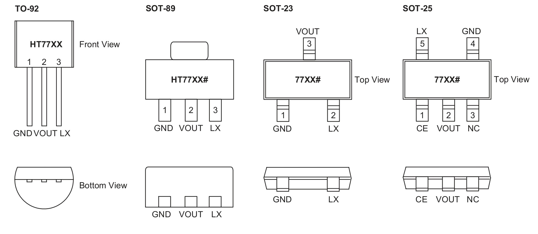
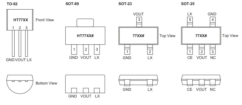
  • TO-92: The classic 3-pin through-hole package, perfect for breadboarding and DIY hobbyist projects.

  • SOT-89: A small surface-mount package with good thermal performance, often found in compact consumer electronics.

  • SOT-23 / SOT-23-5: Ultra-small surface mount options for high-density circuit boards.

    HT77xx TO-92 CAD Model        HT77xx SOT-89 CAD Model        HT77xx SOT-23  CAD Model        HT77xx SOT-25 CAD Model


Technical Specification Overview

Parameter Value
Input Voltage Range 0.85V to 6V
Fixed Output Voltage 5.0V (±2.5% accuracy)
Output Current Up to 200mA (depending on Vin)
Start-up Voltage 0.85V Typical
Switching Frequency Up to 100kHz
Operating Temperature -40°C to 85°C

Pro-Tips for Optimal Performance

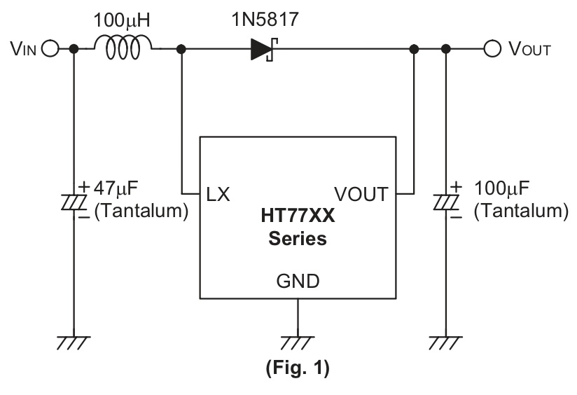
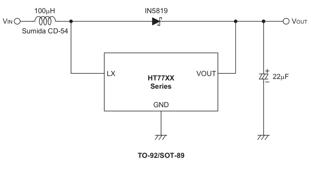
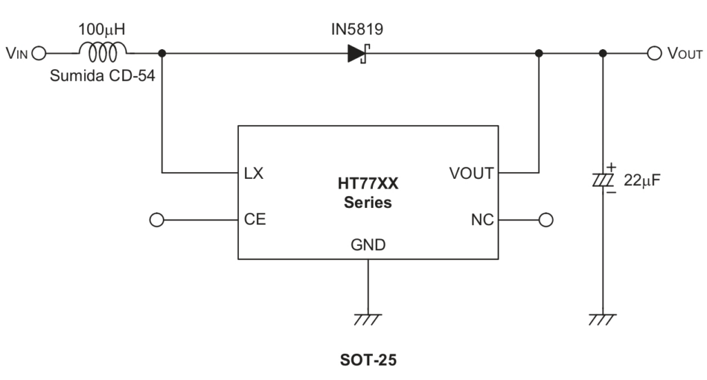
  • The Inductor Choice: Use a low-resistance inductor (typically 47µH to 100µH). A high-quality inductor prevents power loss and ensures the converter hits its maximum efficiency.

  • Schottky Diode: Since the HT7750 is a non-synchronous boost converter in most 3-pin configurations, an external Schottky diode (like the 1N5817 or 1N5819) is required for the rectification process.

  • Input/Output Capacitors: To reduce switching noise, place a 10µF to 47µF tantalum or electrolytic capacitor as close to the input and output pins as possible.

  • Minimal Traces: Keep the “switching loop” (the path between the IC, inductor, and diode) as short as possible to minimize Electromagnetic Interference (EMI).

Common Alternatives

MCP1640, TLV61220, BL8530, ME2108
Read More

78Lxx Series Voltage Regulators: Pinout, Datasheet, and Features Guide {TL00007}

The 78Lxx series is a family of fixed-output linear voltage regulators designed for low-current applications. Often called “universal” regulators, they are found in almost every type of electronic device, from industrial equipment to household appliances. Their primary job is to take a fluctuating or high input voltage and provide a rock-steady, clean output.

This guide explores the full range of the 78Lxx family, covering everything from the popular 5V version to the high-voltage 24V models.


Key Features of the 78Lxx Family

  • Wide Voltage Range: Available in multiple fixed output voltages to suit any circuit.

  • High Input Tolerance: Capable of handling input voltages up to 30V–35V, much higher than LDO regulators.

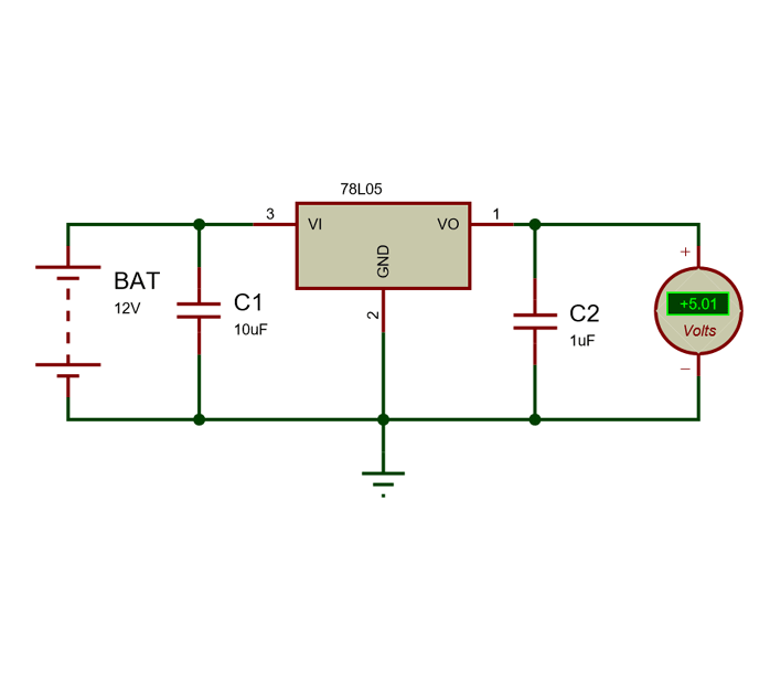
  • Ease of Use: Requires only two external capacitors to function perfectly.

  • Robust Protection: Includes built-in thermal shutdown and internal current limiting to prevent the chip from burning out during a fault.


The 78Lxx Voltage Lineup

The “xx” in the part number represents the output voltage. While they all look the same physically, their internal tuning is different.

1. Common Low-Voltage Models

  • 78L05 (5V)/78L06 (6V): The industry standard for digital logic, microcontrollers, and sensors.

  • 78L08 (8V): Frequently used in audio equipment and older analog signaling.

  • 78L09 (9V)/78L10 (10V): The perfect choice for replacing 9V batteries in portable gadgets.

2. High-Voltage Models

  • 78L12 (12V): Used for powering relays, small DC fans, and LED strings.

  • 78L15 (15V): Common in industrial automation and operational amplifier (Op-Amp) power rails.

  • 78L24 (24V): Used in specialized high-voltage communication interfaces.

Available Packages

Depending on your PCB design, the 78Lxx is available in several form factors:

  1. TO-92 (Through-Hole): The most common “transistor-style” package used by hobbyists and for breadboarding.

  2. SOIC-8 (Surface Mount): A standard 8-pin SMD package used for automated high-volume production.

  3. SOT-89 (Surface Mount): A flat SMD package with a thermal pad for better heat management in compact designs.

                                                                                                       78Lxx TO-92 CAD Model 

    78L05 Datasheet - 5V Positive Voltage Regulator                                   Package: TO92 (Type B)      

                78Lxx  SOIC-8 CAD Model                               78Lxx SOT-89  CAD Model

        SOIC8-N | Toshiba Electronic Devices & Storage Corporation | Asia-English             PG-SOT89-4-2 | Infineon Technologies


Technical Specification Overview

Parameter Value (Standard)
Input Voltage (Max) 30V (for 5V–9V models) / 35V (for 12V–24V)
Output Current 100mA (Max)
Dropout Voltage ~1.7V to 2.0V
Quiescent Current 3mA – 6mA
Operating Temp 0°C to 125°C

Pro-Tips for Universal Integration

  • The “2-Volt” Rule: Always ensure your input voltage is at least 2V higher than your target output. For a 78L05, you need at least 7V input.

  • Polarity Check: Remember that the 78Lxx is for Positive voltages. If you are designing a dual-rail power supply and need a negative version, use the 79Lxx series (e.g., 79L05 for -5V).

  • Thermal Management: Even though they are “universal,” they are not for high power. If you try to drop 24V down to 5V at 100mA, the chip will get very hot (P = (Vin – Vout) \ I).

  • Capacitor Choice: Use ceramic capacitors (0.33μF on input, 0.1μF on output) to ensure the regulator doesn’t “whistle” (oscillate) at high frequencies.

Alternatives for 78Lxx

LM317L (Adjustable version), AMS1117 (LDO version), LP2950 (Low Quiescent), MCP1700

Read More

DW06D Battery Protection IC: Single-Cell Lithium-Ion Safeguard — DW06D {TL00006}

The DW06D is a specialized high-precision lithium battery protection IC designed to ensure the safety and longevity of single-cell lithium-ion/polymer batteries. Compact and efficient, it acts as a safeguard against common battery-related hazards, making it an essential component for portable electronics, power banks, and wearable devices.

This guide explores the technical capabilities, protection thresholds, and package types of the DW06D.

>


Key Features of the DW06D

  • Integrated Protection: Combines overcharge, over-discharge, and overcurrent protection in a single chip.

  • Ultra-Low Quiescent Current: Operates with minimal power consumption (typically 3.0µA) to preserve battery life during storage.

  • High-Accuracy Detection: Features precision voltage detection circuits with a tolerance as low as ±50mV.

  • Automatic Recovery: Designed to automatically restore the battery connection once the fault condition (like a short circuit or over-discharge) is removed.

  • 0V Battery Charging: Capable of allowing a charge even when the battery cell has dropped to near-zero volts.


Protection Varieties and Thresholds

The DW06D is engineered to monitor the battery cell constantly and intervene during the following states:

1. Overcharge Protection Prevents the battery from reaching dangerous voltage levels during charging.

  • Detection Voltage: Typically 4.30V.

  • Release Voltage: Drops to 4.10V before allowing the charging process to resume.

2. Over-discharge Protection Disconnects the load to prevent the battery from discharging below a level that could cause permanent chemical damage.

  • Detection Voltage: Typically 2.40V.

  • Release Voltage: Typically 3.00V.

3. Overcurrent & Short Circuit Protection Monitors the discharge current to protect the battery and the PCB traces from overheating or fire.

  • Overcurrent Detection: Triggers when the load current exceeds the safe operating limit of the internal MOSFETs.

  • Short Circuit Delay: Extremely fast response time (typically 500μs) to prevent catastrophic failure.


Available Packages

The DW06D is designed for space-constrained applications and is primarily available in ultra-small form factors:

  • SOT-23-6: The standard 6-pin surface mount package, ideal for compact battery protection PCBs and small electronic modules.


                DW06D SOT-23-6 CAD Model 

SOT-23 Component Package | mbedded.ninja


Technical Specification Overview

Parameter Value
Input Voltage Range -0.3V to 10V
Operating Current 3.0µA (Typ.)
Overcharge Detection Accuracy ±50mV
Over-discharge Detection Accuracy ±100mV
Operating Temperature -40°C to +85°C
Package Type SOT-23-6

Pro-Tips for Implementation

  • External Components: The DW06D requires very few external parts—usually just one resistor and one capacitor (RC network) to filter out noise from the battery terminals.

  • MOSFET Selection: While the DW06D contains the control logic, it is often paired with external N-channel MOSFETs (like the 8205A) to handle the actual switching of high currents. Ensure your MOSFETs match the current requirements of your load.

  • PCB Layout: Keep the traces between the battery terminals and the IC as short as possible to minimize voltage drops and improve detection accuracy.

Alternatives for DW06D

DW01, DW01A, FS312F-G, HY2110, TP4056 (for combined charging/protection modules)


Read More

Shopping cart

0
image/svg+xml

No products in the cart.

Continue Shopping